Structured Cabling Solutions

Our Solutions
- Complete network solution for Structured Cabling.
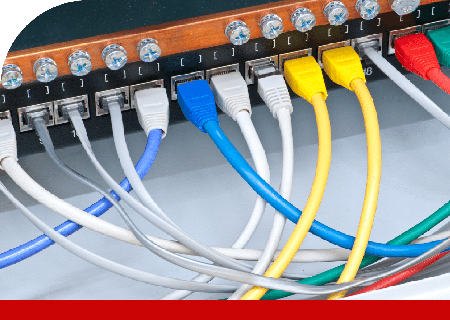
- We provide Supply, installation, trouble shooting, testing & commissioning of UTP, STP Cables, Ethernet switches,Routers, Connectors, Patch Cords, Patch Panels, Racks.
- Engineering Solution for SCN System , including ISP /OSP requirement for Telephone data system.
- Providing Containment, Trunking, conduiting solution for SCN Networks
Efficient Connectivity through Structured Cabling
We are specialized in structured cabling of all kinds, from Category 6/ 6a / 7 to voice block wiring. In house expertise of our network and cabling designs and installation employ the latest technologies and practices, such as CAD, Software Design Tools and the latest standards and practices for project management.
- Supply & Installation
- Supply of accessories & Patch panel
- Trouble shooting
- Testing & Commissioning of UTP
- STI9 FFTP Cable Solution
Structured Cabling Solutions
Structured cabling design and installation is governed by a set of standards that specify wiring data centers, offices, and apartment buildings for data or voice communications using various kinds of cable, most commonly category 5e (CAT-5e), category 6 (CAT-6), and fiber optic cabling and modular connectors.
These standards define how to lay the cabling in various topologies in order to meet the needs of the customer, typically using a central patch panel (which is normally 19 inch rack-mounted), from where each modular connection can be used as needed. Each outlet is then patched into a network switch (normally also rack-mounted) for network use or into an IP or PBX (private branch exchange) telephone system patch panel.
Pan Arabia (PAIS) has very extensive experience in designing and installing standards based structured cabling solutions for large enterprises and we have a large customer base throughout the Middle East.
We have successfully delivered solutions across many industry sectors including Oil & Gas, Construction, Finance, Hospitality, Government, Defense, Telecoms and Utilities. Our certified solutions involve high quality components from leading European and USA manufacturers.
The horizontal cabling system extends from the telecommunications outlet in the work area to the horizontal cross-connect in the telecommunications room. It includes the tele-communications outlet, an optional consolidation point or transition point connector, horizontal cable, and the mechanical terminations and patch cords (or jumpers) that comprise the horizontal cross-connect.
An allowance of 10m (33 ft.) has been provided for the combined length of patchcords/cross-connect jumpers and equipment cables/cords in the HC, including the WA equipment cords.
In ISO/IEC 11801:2002, the equivalent cabling element to the horizontal cross-connect (HC) is called the floor distributor (FD).
Components of a Horizontal Cabling System
- Customer Premises Equipment
- HC Equipment Cord
- Patchcords/cross-connect jumpers used in the HC, including equipment cables/cords, should not exceed 5m (16 ft.).
- Note: ISO/IEC 11801:2002 specifies a max. patchcord/ cross-connect length of 5m (16.4 ft.), which does not include equipment cables/cords.
- Horizontal cable 90m (295 ft.) max. total
- TP or CP (optional)
- Telecommunications outlet/connector (TO)
- Work Area (WA) Equipment cord
Note: An allowance is made for WA equipment cords of 5m (16 ft.).
The backbone cabling system provides interconnections between telecommunications rooms, equipment rooms, main terminal space, and entrance facilities. It includes backbone cables, intermediate and main cross-connects, mechanical terminations, and patch cords or jumpers used for backbone-to-backbone cross-connections. The backbone also extends between buildings in a campus environment.
Some points specified for the backbone cabling subsystem include:
- Equipment connections to backbone cabling should be made with cable lengths of 30m (98 ft.) or less.
- The backbone cabling shall be configured in a star topology. Each horizontal cross-connect is connected directly to a main cross-connect or to an intermediate cross-connect, then to a main cross-connect.
- The backbone is limited to no more than two hierarchical levels of cross-connects (main and intermediate). No more than one cross-connect may exist between a main and a horizontal cross-connect and no more than three cross-connects may exist between any two horizontal cross connects.
- A total maximum backbone distance of 90m (295 ft.) is specified for high bandwidth capability over copper. This distance is for uninterrupted backbone runs. (No intermediate cross-connect).
- The distance between the terminations in the entrance facility and the main cross-connect shall be documented and should be made available to the service provider.
- Recognized media may be used individually or in combination, as required by the installation. Quantity of pairs and fibers needed in individual backbone runs depends on the area served. Recognized backbone cables are: 100 Ω UTP Twisted-Pair, 100 Ω F/UTP Twisted-Pair, 100 Ω S/UTP Twisted-Pair, 50/125μm or 62.5/125μm Multimode Optical Fiber, Single mode optical fiber.
- Multi-pair cable is allowed, provided that it satisfies the power sum crosstalk requirements.
- The proximity of backbone cabling to sources of electromagnetic interference (EMI) shall be taken into account.
- Cross-connects for different cable types shall be located in the same facilities.
Bridged taps and splitters are not allowed.
Pan Arabia (PAIS) provides total In-Building Wireless Systems, including equipment delivery, RF design, construction, and optimization to infrastructure integrators using fully integrated RF tools. Pan Arabia (PAIS) designers have the global expertise to take In-Building Network Designs to new heights while improving accuracy and standardizing design in order to enhance tomorrow’s system requirements.
Pan Arabia (PAIS)’s cost-effective services and 3G mobile network extensions for indoor solutions can be easily and quickly applied to any environment. Our indoor solutions, backed by Pan Arabia (PAIS)’s team of experts, are experienced in cellular/PCS services, broadband and LAN/WAN.
At Pan Arabia (PAIS) Telecom we have chosen to be non-vendor specific which means we work with the widest possible range of equipment providers. This in turn allows us a creative flexibility that facilitates our ability to offer customized planning and design that precisely suits our customers needs.
Our ensemble of technologies enables us to offer a range of in-building services including:
- Wireless Primary & Secondary Broadband Backbones – Pan Arabia (PAIS) offers diverse solutions for wireless coverage projects and overcoming signal difficulties.
- RF Design & Planning – Pan Arabia (PAIS)’s RF Planning Services enhance communication in areas with bad RF expansion and penetration. Pan Arabia (PAIS) is able to cover RF closed coverage circles with microcells, picocells, repeaters, hidden sites and more.
- System Installation & Implementation – Pan Arabia (PAIS) specializes in internal infrastructures; installation of cable guides, communication boxes and special active equipment; deployment and networking of optical, coaxial,and copper cables,
- Project Management & Commissioning – Pan Arabia (PAIS) helps customers to optimize capital investment, improve customer satisfaction and bring in new business.
What is FTTx? : This section explains some of the terminology and architecture commonly associated with FTTx. We hope that you find it useful.
FTTx / Fibre-to-the-x : A generic term for any broadband network architecture that uses optical fibre to replace all or part of the usual metal local loop used for the last mile.
The x can be substituted by another letter determined by the architecture it refers to e.g. FTTN, FTTC, FTTB, FTTH.
FTTx architectures vary with regard to the distance between the optical fibre and the end-user.
FTTN / Fibre-to-the-node
Also can be fibre-to-the-neighbourhood or fibre-to-the-cabinet
Fibre is terminated in a street cabinet up to several kilometers away from the customer premises, with the final ‘last mile’ connection being copper coaxial or twisted pair infrastructure.
Fibre to the node allows delivery of broadband services such as high speed internet. High speed communications protocols such as broadband cable access or some form of DSL are used between the cabinet and the customers. The data rates vary according to the exact protocol used and according to how close the customer is to the cabinet.
FTTC / Fibre-to-the-cabinet or fibre-to-the-curb
Very similar to FTTN, but the street cabinet is closer to the user’s premises; typically within 300m.
FTTB / Fibre-to-the-building or fibre-to-the-basement
Fibre reaches the boundary of the building, such as the basement in a multi-dwelling unit, with the final connection to the individual living space being made via alternative means.
FTTH / Fibre-to-the-home
Fibre reaches the boundary of the living space, such as a box on the outside wall of a home.
Once at the subscriber’s living or working space, the signal may be conveyed throughout the space using any means, including twisted pair, coaxial cable, wireless, power line communication, or optical fibre.
An FTTH network constitutes a fibre-based access network, connecting a large number of end users to a central point known as an access node or point of presence (POP). Each access node is served by a larger metropolitan or urban fibre network, which connect all the access nodes throughout a large municipality or region.
Our FTTx product range provides a wide range of solutions for next generation access networks.
Access networks may connect some of the following:
- Fixed wireless network antenna, for example wireless LAN or WiMAX
- Mobile network base stations
- Subscribers in residential houses, terraces or blocks of flats
- Larger buildings such as schools, hospitals and businesses
- Key security and monitoring structures like surveillance cameras, security alarms and control devices
- Network Applications
The network environment can be broadly split into:
- Intercity/regional
- City
- Campus, business parks, private networks
- Open residential
- Rural
- Building type and density: single homes or multi-dwelling units (MDUs)
The type of site will be a key factor in deciding the most appropriate network design and architecture. Types include:
Greenfield: new build where the network will be introduced at the same time as the buildings
Brownfield: where there are existing buildings and infrastructure but the infrastructure is to a lower standard
Overbuild: adding to the existing infrastructure
The main influences for the infrastructure deployment methodology are:
- type of FTTH area
- size of the FTTH network
- initial deployment cost of the infrastructure elements (CAPEX)
- ongoing costs for network operation and maintenance (OPEX)
- network architecture, for example PON or Active Ethernet
- local conditions, for example, local labour costs, local authority restrictions (traffic control) and others
The fibre deployment technology will determine CAPEX and OPEX, as well as the reliability of the network. These costs can be optimised by choosing the most appropriate active solution combined with the most appropriate infrastructure deployment methodology. These methods include:
- conventional underground duct and cable
- blown microtubes and cable
- direct buried cable
- aerial cable
- ‘other rights of way’ solutions
- FTTH Architecture
In order to specify the interworking of passive and active infrastructure, it is important to make a clear distinction between the topologies used for the deployment of the fibres (the passive infrastructure) and the technologies used to transport data over the fibres (the active equipment).
The two most widely used topologies are point-to-multipoint, which is often combined with a passive optical network (PON) architecture, and point-to-point, typically using Ethernet transmission technologies.
Point-to-multipoint topologies with passive optical splitters in the field are deployed in order to be operated by one of the standardized PON technologies (GPON is today’s frontrunner in Europe, while EPON has been massively deployed in Asia) using time-sharing protocols to control the access of multiple subscribers to the shared feeder fiber. Active Ethernet technology can also be used to control subscriber access in a point-to-multipoint topology – this requires placing Ethernet switches in the field.
Point-to-point topologies provide dedicated fibers between the POP and the subscriber. Each subscriber is directly connected by a dedicated fibre. Most existing point-to-point FTTH deployments use Ethernet, but this can be mixed with other transmission schemes for business applications (for example Fibre Channel, SDH/SONET). This topology can also include PON technologies by placing the passive optical splitters in the access node.

